Milling cutter
Milling cutters are cutting tools typically used in milling machines or machining centres (and occasionally in other machine tools). They remove material by their movement within the machine (e.g., a ball nose mill) or directly from the cutter's shape (e.g., a form tool such as a hobbing cutter).
Contents |
Features of a milling cutter
Milling cutters come in several shapes and many sizes. There is also a choice of coatings, as well as rake angle and number of cutting surfaces.
- Shape: Several standard shapes of milling cutter are used in industry today, which are explained in more detail below.
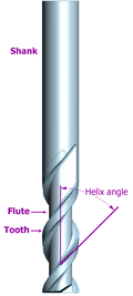
- Flutes / teeth: The flutes of the milling bit are the deep helical grooves running up the cutter, while the sharp blade along the edge of the flute is known as the tooth. The tooth cuts the material, and chips of this material are pulled up the flute by the rotation of the cutter. There is almost always one tooth per flute, but some cutters have two teeth per flute.[1] Often, the words flute and tooth are used interchangeably. Milling cutters may have from one to many teeth, with 2, 3 and 4 being most common. Typically, the more teeth a cutter has, the more rapidly it can remove material. So, a 4-tooth cutter can remove material at twice the rate of a 2-tooth cutter.
- Helix angle: The flutes of a milling cutter are almost always helical. If the flutes were straight, the whole tooth would impact the material at once, causing vibration and reducing accuracy and surface quality. Setting the flutes at an angle allows the tooth to enter the material gradually, reducing vibration. Typically, finishing cutters have a higher rake angle (tighter helix) to give a better finish.
- Center cutting: Some milling cutters can drill straight down (plunge) through the material, while others cannot. This is because the teeth of some cutters do not go all the way to the centre of the end face. However, these cutters can cut downwards at an angle of 45 degrees or so.
- Roughing or Finishing: Different types of cutter are available for cutting away large amounts of material, leaving a poor surface finish (roughing), or removing a smaller amount of material, but leaving a good surface finish (finishing). A roughing cutter may have serrated teeth for breaking the chips of material into smaller pieces. These teeth leave a rough surface behind. A finishing cutter may have a large number (4 or more) teeth for removing material carefully. However, the large number of flutes leaves little room for efficient swarf removal, so they are less appropriate for removing large amounts of material.
- Coatings: The right tool coatings can have a great influence on the cutting process by increasing cutting speed and tool life, and improving the surface finish. Polycrystalline Diamond (PCD) is an exceptionally hard coating used on cutters which must withstand high abrasive wear. A PCD coated tool may last up to 100 times longer than an uncoated tool. However the coating cannot be used at temperatures above 600 degrees C, or on ferrous metals. Tools for machining aluminium are sometimes given a coating of TiAlN. Aluminium is a relatively sticky metal, and can weld itself to the teeth of tools, causing them to appear blunt. However it tends not to stick to TiAlN, allowing the tool to be used for much longer in aluminium.
- Shank: The shank is the cylindrical (non-fluted) part of the tool which is used to hold and locate it in the tool holder. A shank may be perfectly round, and held by friction, or it may have a Weldon Flat, where a grub screw makes contact for increased torque without the tool slipping. The diameter may be different from the diameter of the cutting part of the tool, so that it can be held by a standard tool holder.
Types
End mill
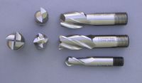
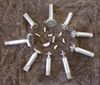
End mills (middle row in image) are those tools which have cutting teeth at one end, as well as on the sides. The words end mill are generally used to refer to flat bottomed cutters, but also include rounded cutters (referred to as ball nosed) and radiused cutters (referred to as bull nose, or torus). They are usually made from high speed steel (HSS) or carbide, and have one or more flutes. They are the most common tool used in a vertical mill.
Slot drill
Slot drills (top row in image) are generally two (occasionally three or four) fluted cutters that are designed to drill straight down into the material. This is possible because there is at least one tooth at the centre of the end face. They are so named for their use in cutting keyway slots. The term slot drill is usually assumed to mean a two fluted, flat bottomed end mill if no other information is given. Two fluted end mills are usually slot drills, three fluted sometimes are not, and four fluted usually are not.
Roughing end mill
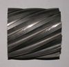
Roughing end mills quickly remove large amounts of material. This kind of end mill utilizes a wavy tooth form cut on the periphery. These wavy teeth form many successive cutting edges producing many small chips, resulting in a relatively rough surface finish. During cutting, multiple teeth are in contact with the workpiece reducing chatter and vibration. Rapid stock removal with heavy milling cuts is sometimes called hogging. Roughing end mills are also sometimes known as ripping cutters.
Ball nose cutter
Ball nose cutters (lower row in image) are similar to slot drills, but the end of the cutters are hemispherical. They are ideal for machining 3-dimensional contoured shapes in machining centres, for example in moulds and dies. They are sometimes called ball mills in shop-floor slang, despite the fact that that term also has another meaning. They are also used to add a radius between perpendicular faces to reduce stress concentrations. There is also a term Bull nose cutter which refers more to a cutter having a corner radius which is less than 1/2 the cutter diameter ie a 20mm diameter cutter with a 1mm radius ground on the corner.
Slab mill
Slab mills are used either by themselves or in gang milling operations on manual horizontal or universal milling machines to machine large broad surfaces quickly. They have been superseded by the use of carbide-tipped face mills which are then used in vertical mills or machining centres.
Side-and-face cutter
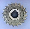
The side-and-face cutter is designed with cutting teeth on its side as well as its circumference. They are made in varying diameters and widths depending on the application. The teeth on the side allow the cutter to make unbalanced cuts (cutting on one side only) without deflecting the cutter as would happen with a slitting saw or slot cutter (no side teeth).
Cutters of this form factor were the earliest milling cutters developed. From the 1810s to at least the 1880s, they were the most common form of milling cutter, whereas today that distinction probably goes to end mills.
Involute gear cutter
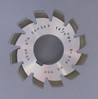
· 10 diametrical pitch cutter
· Cuts gears from 26 through to 34 teeth
· 14.5 degree pressure angle
There are 8 cutters (excluding the rare half sizes) that will cut gears from 12 teeth through to a rack (infinite diameter).
Hob
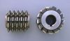
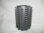
These cutters are a type of form tool and are used in hobbing machines to generate gears. A cross section of the cutters tooth will generate the required shape on the workpiece, once set to the appropriate conditions (blank size). A hobbing machine is a specialised milling machine.
Face mill
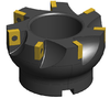
A face mill consists of a cutter body (with the appropriate machine taper) that is designed to hold multiple disposable carbide or ceramic tips or inserts, often golden in color. The tips are not designed to be resharpened and are selected from a range of types that may be determined by various criteria, some of which may be: tip shape, cutting action required, material being cut. When the tips are blunt, they may be removed, rotated (indexed) and replaced to present a fresh, sharp face to the workpiece, this increases the life of the tip and thus their economical cutting life.
Fly cutter
A fly cutter is composed of a body into which one or two tool bits are inserted. As the entire unit rotates, the tool bits take broad, shallow facing cuts. Fly cutters are analogous to face mills in that their purpose is face milling and their individual cutters are replaceable. Face mills are more ideal in various respects (e.g., rigidity, indexability of inserts without disturbing effective cutter diameter or tool length offset, depth-of-cut capability), but tend to be expensive, whereas fly cutters are very inexpensive.
Woodruff cutter
Woodruff cutters are used to cut the keyway for a woodruff key.
Hollow mill
Hollow milling cutters, more often called simply hollow mills, are essentially "inside-out endmills". They are shaped like a piece of pipe (but with thicker walls), with their cutting edges on the inside surface. They are used on turret lathes and screw machines as an alternative to turning with a box tool, or on milling machines or drill presses to finish a cylindrical boss (such as a trunnion).
Dovetail cutter
A dovetail cutter is an endmill whose form leaves behind a dovetail slot.
Using a milling cutter
Chip formation
Although there are many different types of milling cutter, understanding chip formation is fundamental to the use of any of them. As the milling cutter rotates, the material to be cut is fed into it, and each tooth of the cutter cuts away small chip of material. Achieving the correct size of chip is of critical importance. The size of this chip depends on several variables.
- Surface cutting speed (Vc): This is the speed at which each tooth cuts through the material as the tool spins. This is measured either in metres per minute in metric countries, or surface feet per minute (SFM) in America. Typical values for cutting speed are 10m/min to 60m/min for some steels, and 100m/min and 600m/min for aluminum. This should not be confused with the feed rate.
- Spindle speed (S): This is the rotation speed of the tool, and is measured in revolutions per minute (rpm). Typical values are from hundreds of rpm, up to tens of thousands of rpm.
- Diameter of the tool (D):
- Feed per tooth (Fz): This is the distance the material is fed into the cutter as each tooth rotates. This value is the size of the deepest cut the tooth will make.
- Feed rate (F): This is the speed at which the material is fed into the cutter. Typical values are from 20mm/min to 5000mm/min.
- Depth of cut: This is how deep the tool is under the surface of the material being cut (not shown on the diagram). This will be the height of the chip produced. Typically, the depth of cut will be less than or equal to the diameter of the cutting tool.
The machinist needs three values: S, F and Depth when deciding how to cut a new material with a new tool. However, he will probably be given values of Vc and Fz from the tool manufacturer. S and F can be calculated from them:
| Spindle Speed | Feed rate |
|---|---|
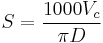 |
 |
| Looking at the formula for the spindle speed, S, it can be seen that larger tools require lower spindle speeds, while small tools may be able to go at high speeds. | The formula for the feed rate, F shows that increasing S or z gives a higher feed rate. Therefore, machinists may choose a tool with the highest number of teeth that can still cope with the swarf load. |
Conventional milling versus climb milling
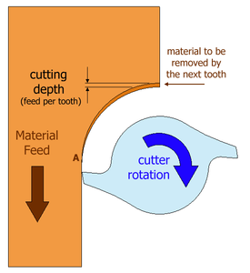
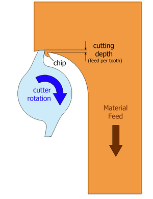
A milling cutter can cut in two directions, sometimes known as conventional or up and climb or down.
- Conventional milling (left): The chip thickness starts at zero thickness, and increases up to the maximum. The cut is so light at the beginning that the tool does not cut, but slides across the surface of the material, until sufficient pressure is built up and the tooth suddenly bites and begins to cut. This deforms the material (at point A on the diagram, left), work hardening it, and dulling the tool. The sliding and biting behaviour leaves a poor finish on the material.
- Climb milling (right): Each tooth engages the material at a definite point, and the width of the cut starts at the maximum and decreases to zero. The chips are disposed behind the cutter, leading to easier swarf removal. The tooth does not rub on the material, and so tool life may be longer. However, climb milling can apply larger loads to the machine, and so is not recommended for older milling machines, or machines which are not in good condition. This type of milling is used predominantly on mills with a backlash eliminator.
Swarf removal
Another important quality of the milling cutter to consider is its ability to deal with the swarf generated by the cutting process. If the swarf is not removed as fast as it is produced, the flutes will clog and prevent the tool cutting efficiently, causing vibration, tool wear and overheating. Several factors affect swarf removal, including the depth and angle of the flutes, the size and shape of the chips, the flow of coolant, and the surrounding material. It may be difficult to predict, but a good machinist will watch out for swarf build up, and adjust the milling conditions if it is observed.
Selecting a milling cutter
Selecting a milling cutter is not a simple task. There are many variables, opinions and lore to consider, but essentially the machinist is trying to choose a tool which will cut the material to the required specification for the least cost. The cost of the job is a combination of the price of the tool, the time taken by the milling machine, and the time taken by the machinist. Often, for jobs of a large number of parts, and days of machining time, the cost of the tool is lowest of the three costs.
- Material: High speed steel (HSS) cutters are the least-expensive and shortest-lived cutters. Cobalt steel is an improvement on HSS and generally can be run 10% faster. Carbide tools are more expensive than steel, but last longer, and can be run much faster, so prove more economical in the long run. HSS tools are perfectly adequate for many applications. The progression from HSS to cobalt steel to carbide could be viewed as very good, even better, and the best.
- Diameter: Larger tools can remove material faster than small ones, therefore the largest possible cutter that will fit in the job is usually chosen. When milling an internal contour, or concave external contours, the diameter is limited by the size of internal curves. The radius of the cutter must be less than or equal to the radius of the smallest arc.
- Flutes: More flutes allows a higher feed rate, because there is less material removed per flute. But because the core diameter increases, there is less room for swarf, so a balance must be chosen.
- Coating: Coatings, such as Titanium nitride, also increase initial cost but reduce wear and increase tool life.
- Helix angle: High helix angles are typically best for soft metals, and low helix angles for hard or tough metals.
History
The history of milling cutters is intimately bound up with that of milling machines. Milling evolved from rotary filing, so there is a continuum of development between the earliest milling cutters known, such as that of Jacques de Vaucanson from about the 1760s or 1770s,[2][3] through the cutters of the milling pioneers of the 1810s through 1850s (Whitney, North, Johnson, Nasmyth, and others),[4] to the cutters developed by Joseph R. Brown of Brown & Sharpe in the 1860s, which were regarded as a break from the past[5][6] for their large step forward in tooth coarseness and for the geometry that could take successive sharpenings without losing the form of the cut. De Vries (1910)[6] reported, "This revolution in the science of milling cutters took place in the States about the year 1870, and became generally known in Europe during the Exhibition in Vienna in 1873. However strange it may seem now that this type of cutter has been universally adopted and its undeniable superiority to the old European type is no longer doubted, it was regarded very distrustfully and European experts were very reserved in expressing their judgment. Even we ourselves can remember that after the coarse pitched cutter had been introduced, certain very clever and otherwise shrewd experts and engineers regarded the new cutting tool with many a shake of the head. When[,] however, the Worlds Exhibition at Philadelphia in 1876, exhibited to European experts a universal and many-sided application of the coarse pitched milling cutter which exceeded even the most sanguine expectations, the most far-seeing engineers were then convinced of the immense advantages which the application of the new type opened up for the metalworking industry, and from that time onwards the American type advanced, slowly at first, but later on with rapid strides".[7]
Woodbury provides citations[8] of patents for various advances in milling cutter design, including irregular spacing of teeth (1867), forms of inserted teeth (1872), spiral groove for breaking up the cut (1881), and others. He also provides a citation on how the introduction of vertical mills brought about wider use of the endmill and fly cutter types.[9]
Scientific study by Holz and De Leeuw of the Cincinnati Milling Machine Company[10] made the teeth even coarser and did for milling cutters what F.W. Taylor had done for single-point cutters with his famous scientific cutting studies.
References
- ↑ Rapid Traverse: More Teeth Per Flute
- ↑ Woodbury 1972, p. 23.
- ↑ Roe 1916, p. 206.
- ↑ Woodbury 1972, pp. 51-52.
- ↑ Woodbury 1972, pp. 51-55.
- ↑ 6.0 6.1 De Vries 1910, p. 15.
- ↑ De Vries 1910, pp. 15-16.
- ↑ Woodbury 1972, p. 54.
- ↑ Woodbury 1972, pp. 54-55.
- ↑ Woodbury 1972, pp. 79-81.
Bibliography
- De Vries, D. (1910), Milling machines and milling practice: a practical manual for the use of manufacturers, engineering students and practical men, London: E. & F.N. Spon, http://books.google.com/books?id=d0rOAAAAMAAJ&pg=PR3#v=onepage&q&f=false. Coedition, New York, Spon & Chamberlain, 1910.
- Roe, Joseph Wickham (1916), English and American Tool Builders, New Haven, Connecticut, USA: Yale University Press, LCCN 16-011753, http://books.google.com/books?id=X-EJAAAAIAAJ&printsec=titlepage. Reprinted by McGraw-Hill, New York and London, 1926 (LCCN 27-024075); and by Lindsay Publications, Inc., Bradley, IL, USA (ISBN 978-0-917914-73-7).
- Woodbury, Robert S. (1972) [1960], History of the Milling Machine. In Studies in the History of Machine Tools, Cambridge, Massachusetts, USA, and London, England: MIT Press, LCCN 72-006354, ISBN 978-0-262-73033-4. First published alone as a monograph in 1960.
|
|||||||||||||||||||||||||||||||
|
||||||||||||||||||||||||||